Understanding P&id Drawings
Understanding p&id drawings ~ Figure 17 is a representative PID for the distillation section of the benzene process shown in Figure 15The PID presented in Figure 17 provides information on the piping and this is included as part of the diagram. A very detailed diagram showing the processes happening within a plant the involved equipment and their interconnections. Indeed recently has been searched by consumers around us, maybe one of you personally. People now are accustomed to using the internet in gadgets to see video and image data for inspiration, and according to the name of the post I will talk about about Understanding P&id Drawings Each PFD will require many PIDs to provide the necessary data.
If you re searching for Understanding P&id Drawings you've come to the perfect place. We have 9 graphics about understanding p&id drawings adding images, pictures, photos, backgrounds, and more. In these web page, we also provide variety of graphics available. Such as png, jpg, animated gifs, pic art, symbol, black and white, transparent, etc.

Understanding p&id drawings - There are different Sets of symbols are used to depict mechanical equipment piping piping components valves drivers and instrumentation and controls. Piping and Instrumentation Diagrams commonly referred to as PIDs are encountred nowadays throughout all process industries such as Oil Gas chemical pharmaceutical or food industries. Before moving to the actual drawing you will learn PID symbols that are used in these drawings. As an alternative each pipe can be numbered and the specifics of every line can be.
Through a PID you can get the following information. And their respective control schemes in relation to the elements of the plant and its interconnection pipes. In this Article we will develop the rule of how to read PID. Step 4 Know PID Symbols.
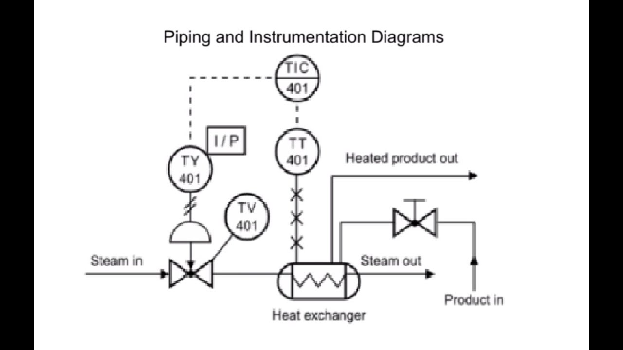
Understanding a PID Layout. Piping and instrumentation diagram also called PID is a diagram used to show a graphical display of a complete system. PID is the acronym for Piping and instrumentation diagram ie. Such diagrams are famous in the engineering field.

A Piping And Instrumentation Diagram P Id Is A Schematic Illustration Of Functional Relation Piping And Instrumentation Diagram P Id Diagram Drawing Examples

P Id Guidelines For Centrifugal Compressor Systems Centrifugal Compressor P Id Diagram Compressor

Flowchart Maker How To Read Piping And Instrumentation Diagram Piping And Instrumentation Diagram Diagram P Id Diagram
How To Read Piping And Instrumentation Diagram P Id Piping And Instrumentation Diagram P Id Diagram Diagram
How To Read Piping And Instrumentation Diagram P Id Piping And Instrumentation Diagram P Id Diagram Diagram

What Is A P Id Diagram In Laymen S Term Realpars P Id Diagram Diagram Piping And Instrumentation Diagram

What Is Piping And Instrumentation Diagram P Id Piping And Instrumentation Diagram Mechanical Engineering Design P Id Diagram

How To Read Piping And Instrumentation Diagram P Id Diagram Piping And Instrumentation Diagram Mind Mapping Tools
They are typically created by engineers who are designing a manufacturing process for. A piping and instrumentation diagram PID is a graphic representation of a process system that includes the piping vessels control valves instrumentation and other process components and equipment in the system. Your Understanding p&id drawings pictures are ready. Understanding p&id drawings are a topic that has been hunted for and liked by netizens today. You can Find and Download or bookmark the Understanding p&id drawings files here
No comments for "Understanding P&id Drawings"
Post a Comment